Nerd developing at home, with the style of Nicolas de Staël, courtesy of Stable Diffusion
Working with Quasar (Vue.js based) is a bliss for Web UI / SPA / etc… development. Especially is you use Vite, for the speed of site build. I highly recommend it. Now vercel makes it super easy to host and test your app online.
Here is a little problem I encountered, so I’m sharing (so that the monster Internet search engines that swallow everything can index this little helper blog post).
Contrary to what you can find in Quasar Documentation, namely here, the vercel.json file content should not be:
(My pull request to quasar to fix this was accepted and is now fixed in their doc)
Basically it’s because you don’t know that it’s gonna be an index.html handling the traffic: it’s not. It’s the application residing at / that handles everything.
You need to have a HAM (Radio Amateur) license to transmit (yes, even a few milli-Watts (mW) or radiated power), but good news is that it’s the best time right now to pass your HAM license:
France has just changed its license test method so that bad answer don’t cost you points, and you can repeat (cram) exams so it’s not that difficult.
US has a much better and more progressive license scheme (Technician -> General -> Amateur Extra) and excellent teaching resources that makes it so much easier to get started.
… and you’ve got plenty of time to prepare for exams since you can’t get out due to this covid-19 lockdown 🙂
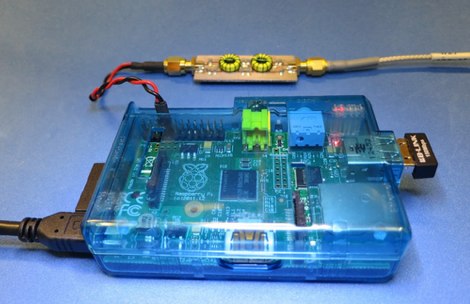
Now if you look at the picture above, there’s a little circuit between the RPi and the antenna… why is that?
On being clean…
Well, the RPi was never intended to directly output radio signal, so it generates a square wave with plenty of harmonics (unwanted frequencies above the desired generated radio frequencies) that pollute the spectrum if you connect the RPi output directly to the antenna.
NOTE: Having the privilege of sending radio waves worlwide comes with some small obligation: send clean radio signals! Don’t hurt your neighbour communications! Don’t force governments and regulators to limit our radio spectrum freedoms because we couldn’t self regulate. So far, HAM enthusiasts have done a great job not killing our radio passion. If you join, or plan on joining, please do the same.
Available Filters
So there are plenty of designs to make this output clean:
TAPR WSPR RPI Hats that work with their RPi OS image to transmit on various frequencies (20m wavelength (14 MHz): 14.070 MHz – 14.350 MHz for weak signal digital communications, 30m (10MHz): 10.130 – 10.150 MHz for weak signal digital communications, 40m (7MHz)).
Ok, if this looks like foreign unknown language, don’t worry, we’ll explain step by step.
DIY Filter
Now the goal of experimentation is to learn by yourself and make your own stuff, so below is the documentation of a design in progress (fun in progress? some people will call us crazy) of a custom filter, by non-electronicians, for the RPi. (You’ll see that we go slowly and step by step over the process we used, so that it’s easy to follow and reproduce).
The goal of this filter is to:
Learn about filters and electronic and RF,
work on 7 MHz,
for WSPR low signal (therefore low power, therefore we can maybe use some components such as Axial Fixed Inductors that are only for 0.25 W or 0.5W or 1W),
be built with low part number,
low complexity,
with easy to procure and to solder electronic components: no or low CMS, no exotic part numbers, no need to print a PCB mandatorily…
if possible no coil-winding (building the inductive coils),
if possible with protection of the RPi from static electricity coming from the antenna.
work on the RPi Zero W.
Actually, the goal of this post is to discuss between passionate individuals and critique the filter design(s) presented here, rather than providing a clean design.
So if you’re expecting a clean, profesionnal, working filter, this is maybe not the place.
Also, the goal is to document the (rather numerous) f..k-ups and mistakes we’ve done along the way, with their associated lessons-learned:
Using RC filter: originally selected because it is announced as the simplest filters, it worked but was extremely low-power output, due to to the very nature of Resistive-Capacitive (RC) filters, yeah, it resists and dissipates heat, therefore weakening to radio output power… logical.. Replace with Inductive Capacitive (LC) filter.
RPi can generate radio signals for a variety of bands, up to the FM band (around 100 MHz radio signal). This means that you have quite a lot of HAM bands (Legacy or WARC) you can use. The lower the HAM radio frequency, the bigger the antenna, the farther you can expect it to go: HF (3 MHz-30 MHz) can travel across oceans, VHF (30 MHz-300MHz) – UHF (300 MHz – 3000 MHz or 3GHz) range is only a few kilometers in usual conditions.
Usually antennas are one fourth or half the wavelength, so if you’re operating on 7 MHz, the 40 m band, you can expect your antenna to be from 10 meters to 20 meters wide, or high, or both.
That means that you usually choose your operating frequency based on the space you have. Typically, in cities, you will probably choose higher frequencies with smaller antennas.
And based on your antenna, you will pick a filter that is allowing only frequencies for this antenna to exit the RPi and go to the antenna.
Building an antenna is a lot of fun, and antennas are so varied, up to the ones that enable you to receive from and transmit to a satellite. It’s much easier than you initially think. We’ll have plenty of episodes related to antenna building.
So let’s build a filter… and please give us feedback
There are many types of filters, as stated earlier. We started with a RC filter but the drop in desired radio signal output power was too important, therefore prompting to choose another filter, an LC filter that should preserve better the desired radio signal power and still be somewhat simple to build with common components.
Of these LC filters, we choose a Butterworth pass-band filter, for its apparent simplicity. Critique is welcome.
Pass band means that only one range of frequency can go through. It’s opposed to Low-Pass Filters (LPF: Only frequency below the cut-off frequency can go through) or High-Pass Filters (only frequencies above the cut-off frequency can go through the filter).
$ brew tap guitorri/tap $ brew tap cartr/qt4 $ brew install qucs $ brew link qucs
Regarding installation on Linux, qucs was not in the APT packages of RPi. That’s because its Debian package was abandoned a few years ago. A lab member successfully compiled it using the official qucs wiki page on an AMD64 Debian 9 though, so there’s hope it might works on most distributions.
After this, we launch QUCS:
$ qucs &
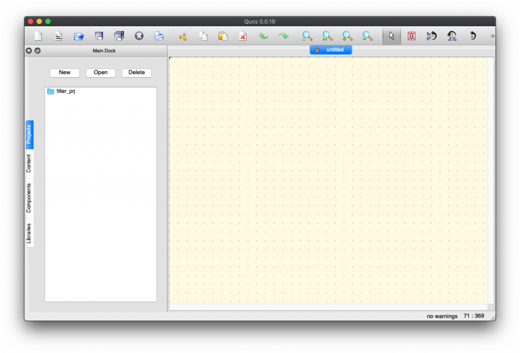
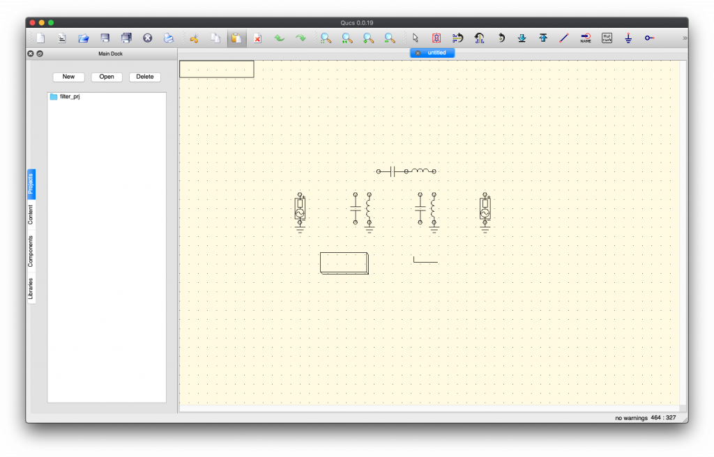
First fun is that QUCS runs but isn’t launched in the foreground, you need to Alt-Tab or Command-Tab to select its icon to see its window (otherwise you spend a good amount of time saying “wow… must be super awesome large software that takes ages to start… really long… such 31337 software…”. actually QUCS is quite quick to launch!):
To see larger version of these screen shot, just right click on the image and select “Open image in new tab” and switch to that tab. Full size yeah!!!
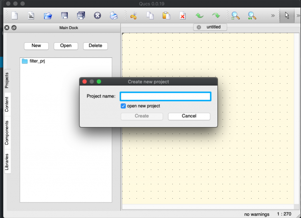
Then you can (and should) create a new project by Clicking “New” in the “Projects” side tab (here already created as you already see filter_prj).
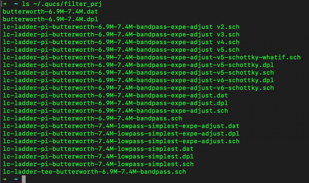
It corresponds actually to the folder ~/.qucs/<project_name> directory under which you’ll save all your schema files (*.sch). Creating the project directory will prevent some runtime errors when running simulations. Go ahead, create one and work there.
You can see above my quasi-OCD (Obsessive Compulsive Disorder) maniac naming style 😉
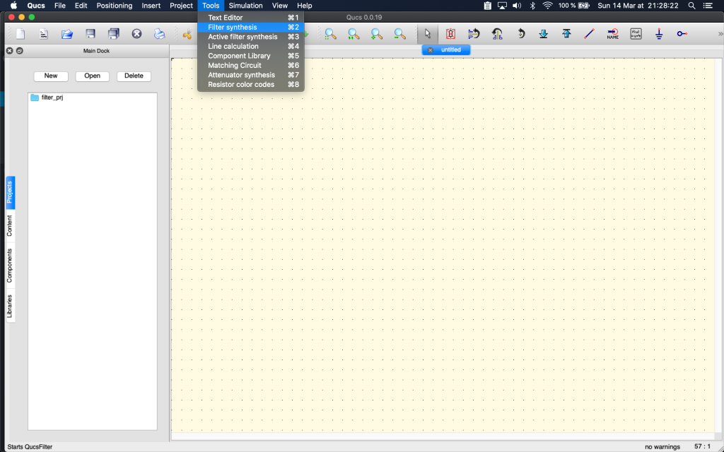
Then you go to Menu > Tools > Filter Synthesis:
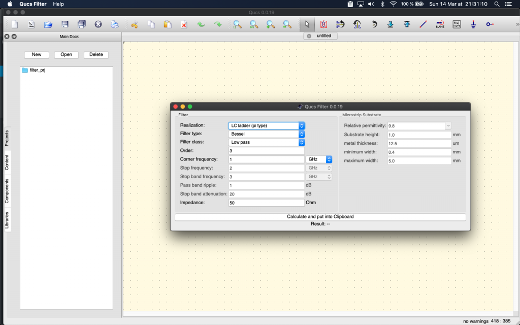
Qucs Filter is then run, but same thing as QUCS run, also often stays in the background. You’ll have to press ALT-TAB or Command-Tab to change window focus to it.
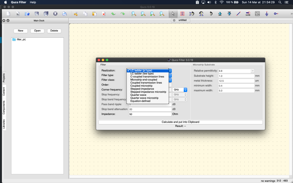
We choose LC Ladder (PI Type). Why? No idea. Suggestions are welcome. (In reality we rummaged through many web pages and many QUCS choices, comparing resulting filters with the simplest designs that were shown on the Net, before settling on this choice). Suggestions (and rationale) are really welcome about this.
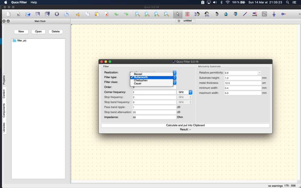
Then we change default type (Bessel) to Butterworth as it seems also to be a recommended LC type filter. (lessons learned not to use a RC filter and avoid signal power drops).
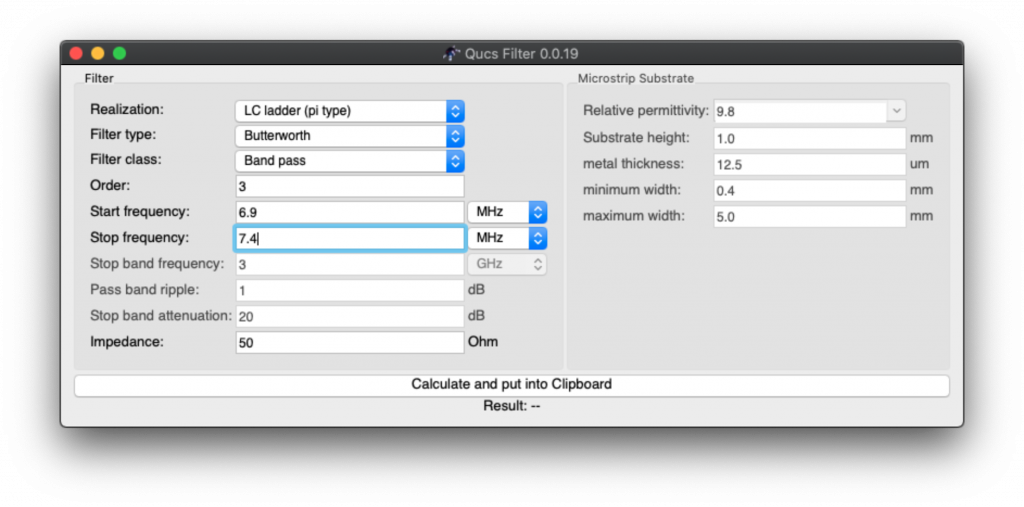
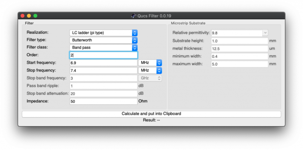
Then change default from Low Pass to Band Pass, and adapt start and stop frequencies, allowing for some “buffer space” around desired frequency.
Why this buffer space? because we’re going later to tweak values of electronic components to adjust with what we can easily buy, and therefore this will have an impact on the resulting frequencies that are allowed (that “pass”) or that are attenuated. Hence the choice to have some space around the 7 MHz HAM band frequencies.
The good thing is that the process described here works for all bands, you just need to adjust the values we’re specifying here. So if you want to build a filter for other frequencies, you can use this method and free software.
Here QUCS Filter with selected filters options and the frequencies input in MHz (note we changed the default frequency unit from GHz to MHz):
Then click “Calculate”
If you think nothing happens, well… you’re part right. It copied “something” (the result of filter computations) in the clipboard… then you need to switch to QUCS… and paste there in an empty circuit schema (Control-V or Command-V). A circuit skeleton will appear under your mouse cursor and hover on top of the schema for positioning of the filter result. That’s QUCS UX (User eXperience):
Move your mouse pointer to where you want your filter schema and click (Normal left click) to position it where you want on your page:
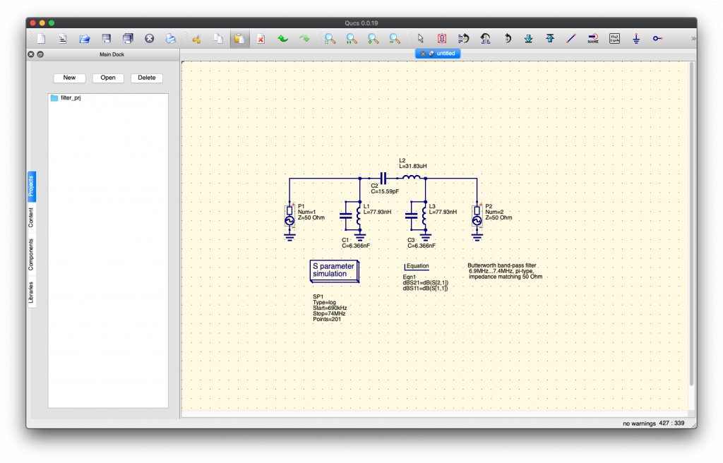
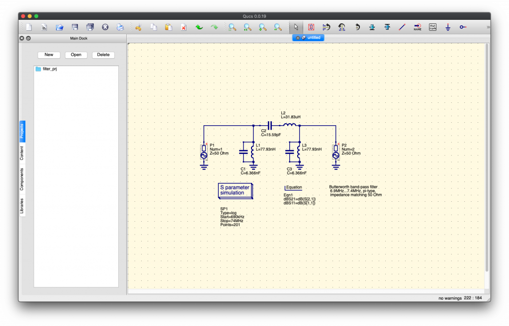
Tadaaa… the magic results appears on QUCS ! Argh… foreign unknown language again? We’ll explain later the schema.
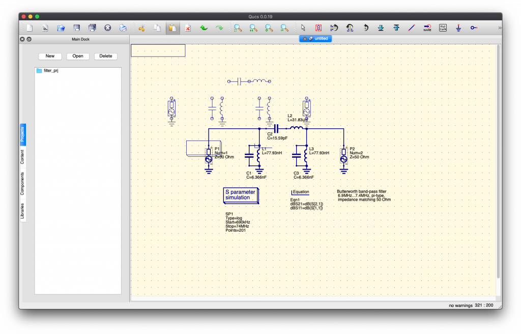
But if you continue moving your mouse, you’ll see that a copy of the filter is still selected, appearing as a skeleton (and can again be applied):
Yes… this is troubling UX. Just press ESC to deselect it (or “forget” it), it’s ok, one copy is enough and it is already there on your schema.
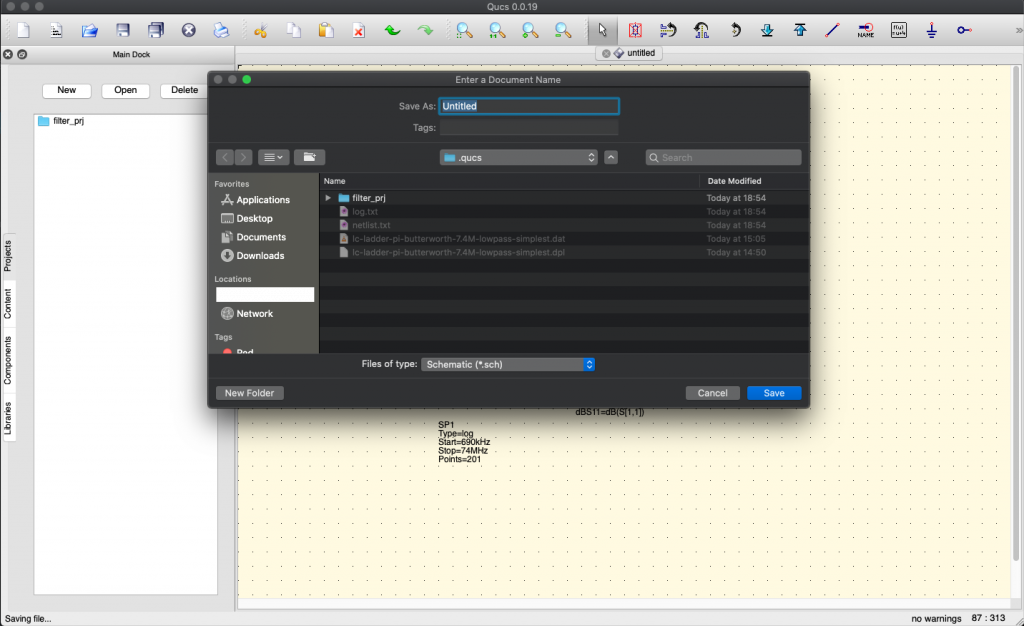
You can go ahead and save this:
Please note that we choose to limit the amount of electronic components in the final circuit schema by selecting in the QUCS filter not “Order = 3” but to “Order = 2”:
so yeah, you’ll need to repeat the process of generating a filter… that’s training 😉
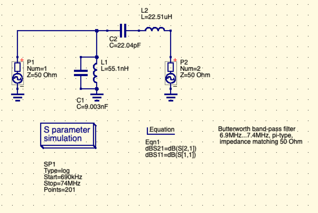
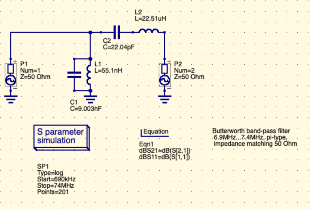
Resulting in this simplified schematics (with less electronic components):
Simpler isn’t it? — See, we have one less leg toward the ground with one less inductance “coils” and one less capacitor. Please also note that the remaining inductance and capacitor values have changed.
We don’t know really the impact of such choice, so don’t hesitate to tell us. It looked like the only visible impact (visible during simulation) was that the filtered signal would go closer to full values (1x the passed signal, 0x power of filtered values) with order=3, which means that our choice of order=2 means that the filtering nor the pass-through will be complete. That means that a small attenuation of the allowed band would still be applied by the circuit. It means also that the filtering would be less “selective” than and third-order circuit. It’s not so bad since at these very low power (RPi outputs only in the mW range), the attenuation of these very lower spurious signals is really sufficient and would not radiate enough to be a real RF interference to other radio spectrum users. Please tell us if we’re wrong!
As we understand this schema:
P1 (Port 1) is the generator, that is the TX output, the transmitter output:
Please note that it may be confusing as you see sometime “TX” label on some electronic schema for the input of the filter. It should be labeled “From TX” or “TX Output”.
P2 (Port 2) is the antenna (ANT).
It is also called sometime the “load” as you can output the radio signal to a resistive load to simulate an antenna (and avoid frying transmitters if they’re powerful enough and not connected to any “load”).
It’s very useful during design as it prevents badly designed filters from emitting real RF to an antenna.
Consider this when you start.
The antenna is really the output of the filter.
A little reminder on electronic components
Electronic components on a schema are prefixed by a letter that indicate the type of component, and then a number that indicates its identification on the schema and the value of such electronic component.
Let’s see common type of electronic components used here:
L: Inductors or Coils (“Bobines” or “Inductances” in french), these “store” energy as magnetic energy and give it back to the circuit.
There are many inductors types, most of the time these are coils of copper wire around a metallic ring “core”.
These are often used in transformers and amplifiers such as audio rigs, old power transformers, etc..
Some types are looking like resistors (one ceramic package traverse by a wire that is exposed on both sides)
C: Capacitors (“Condensateurs” in french), these “store” energy as electricity field energy and give it back to the circuit.
R: Resistors (“Resistances” in french), these pressure and limit the passage of electricity in a way that changes the Voltage (“E” in english, “U” in french) and Intensity (I).
There should be no specific resistor in filter circuits because resistors resists (!) and doing so, they heat up.
The heat is actually radio signal power that dissipates.
I.e.: the filter makes the whole radio signal power a bit weaker (or a lot weaker)
The look of resistors (one ceramic package traverse by a wire that is exposed on both sides) is very common. It’s often called the “through hole” packaging, since now there are surface mount (SMD) versions of it.
Let’s simulate now our new filter !
Now we have a filter, let’s see how it behaves in front of input frequencies. Nothing is better than a graph to “see” your filter. Here is how to generate this filter graph through simulation.
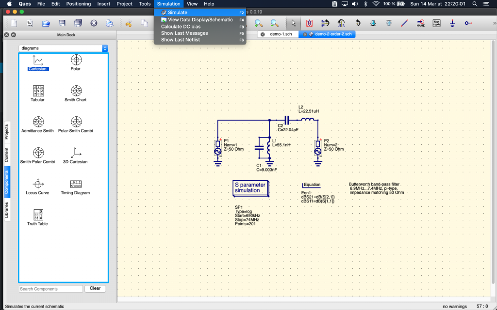
We click on Menu > Simulation > Simulate (or type F2):
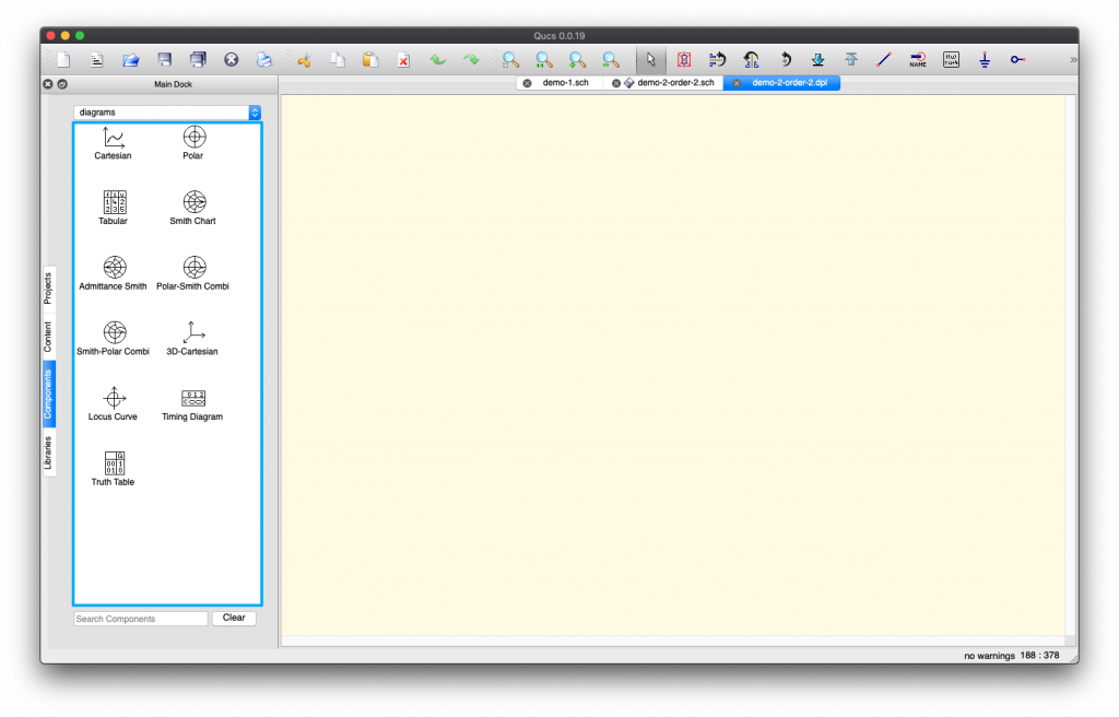
A new screen appears… But nothing happens: no simulation result.
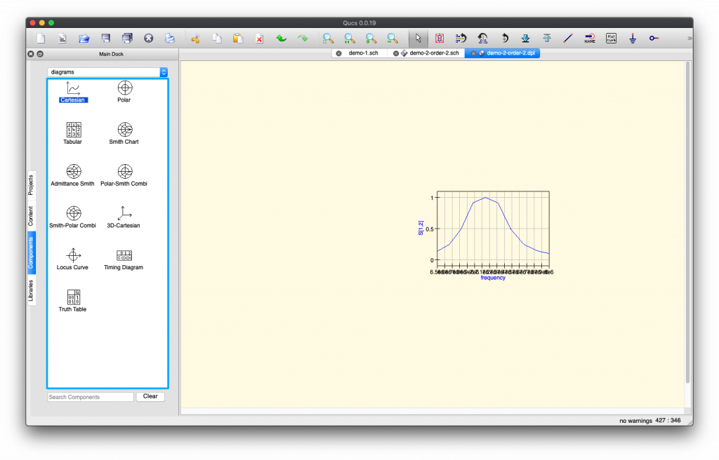
This is normal, QUCS is just waiting for you to chose which kind of simulation result you want to see. We’re going to chose Cartesian representation diagram, but the most elite radio guys will choose Smith (cuz it looks so cool! kidding aside, it must be awesome but it’s easier for newbies like us to read the simple graph):
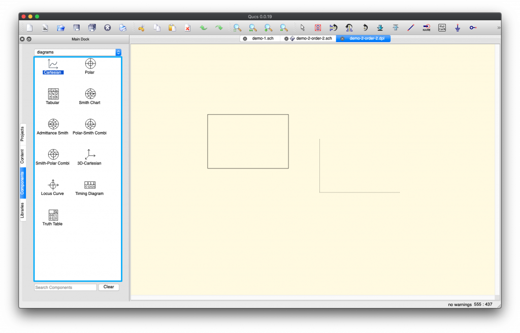
Once you click on “Cartesian” and hover on the window, you see a “skeleton” of the result appear and follow you mouse. Just click (left click) once to instantiate the result, an option window should appear.
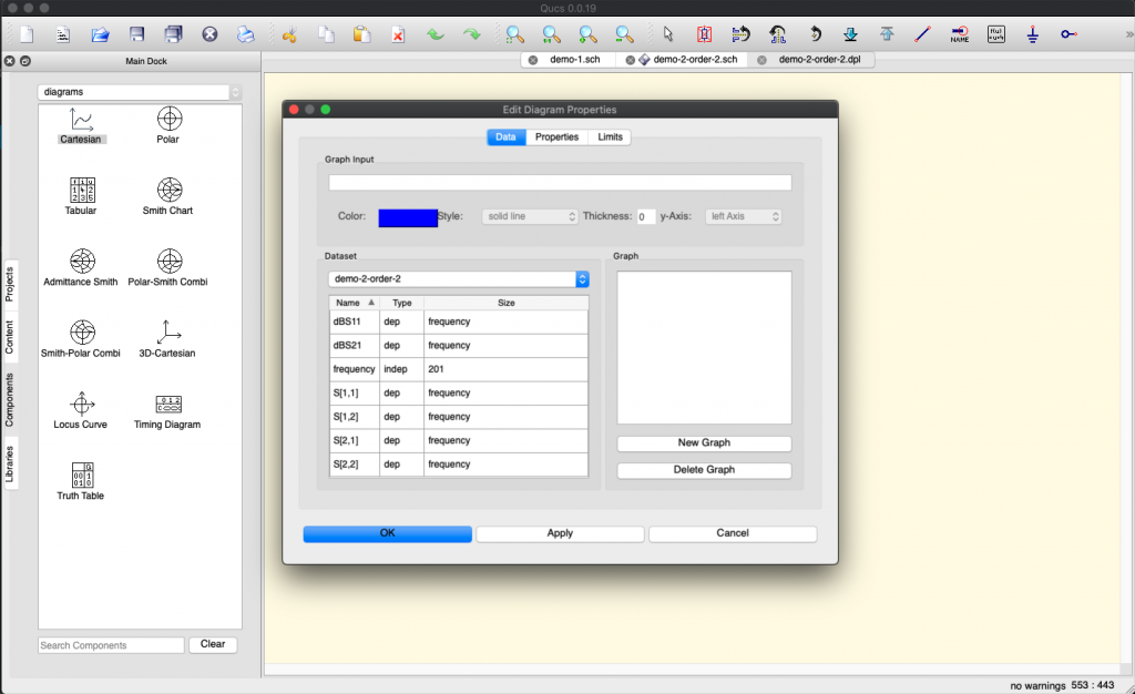
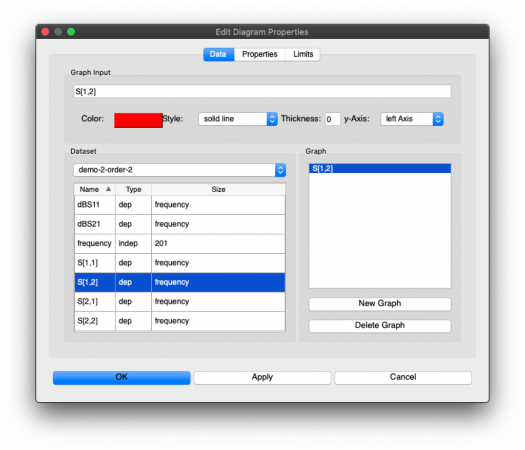
Now you need to set a few things for the simulation to run and result to appear.
First you need to say which signals you want to be graphed. Here what we understand is that S[1,2] is the filter output signal (i.e. the filtered signal). So we’re going to double click on S[1,2] to add it to the Graph:
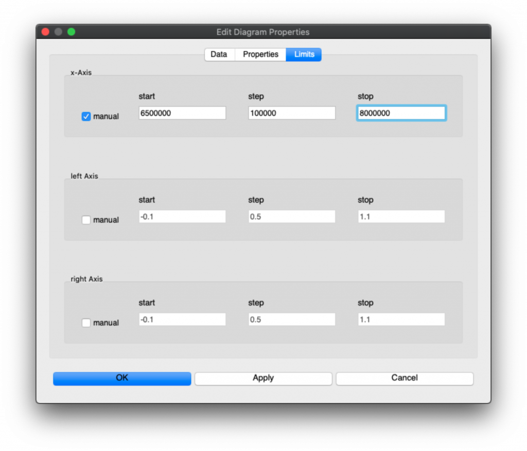
But it’s not finished, we now need to restrict the Limits of the graph to only the portion of the simulation we’re interested in. So Click on Limits, Select Manual input for x-Axis:
The values we selected are in Hertz (Hz) and quite large around the band so that we clearly see the filter output, and the step (100,000) is to prevent cluttering the graph.
Then click “OK”. You’ll see a tiny graph appear.
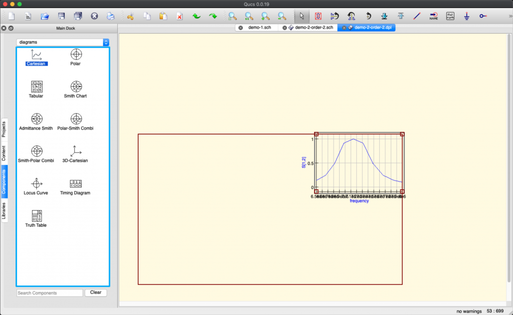
You can drag the corners by clicking into the graph and select one corner to drag in order to enlarge the graph:
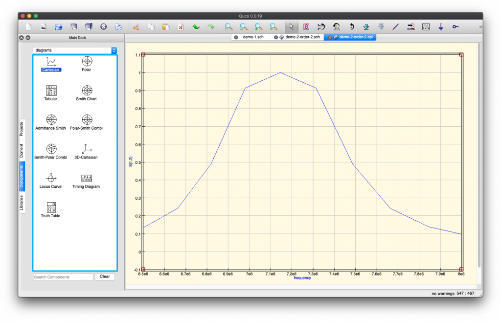
Then you have a nice result where you see in which frequencies your filter let’s the maximum of the signal go through:
We see that the band of frequencies specified is respected and let through by the filter, while the levels of other frequencies are very much attenuated. To read this diagram, the value on the Y-axis (on the left) is the number of times the power that goes through. The X-axis is the frequency. 7.1e6 corresponds to 7.1*1,000,000 Hz = 7.1 MHz
Now we need to adjust the components
As you’ll see, the values of components are not standardised values, and we need to change some of the components values to match what we can find in shops.
So we’ll do one change, save, run a simulation and check that the effect on the filter is not so bad. Not so bad effect means:
The filter still filters approximatively the same frequencies (same cut-offs)
The filtering level is still the same (around 0.1x of the signal or better)
The allowed (passed) signals are still around the same levels (0.9 or better)
So the raw values we had without adjustment of electronic components were:
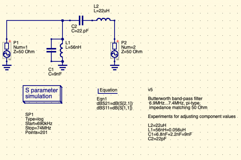
Here is the adjusted graph we end up with:
All these values of components we can find in shops, except the L1 inductor that we can’t find. Suggestions welcome.
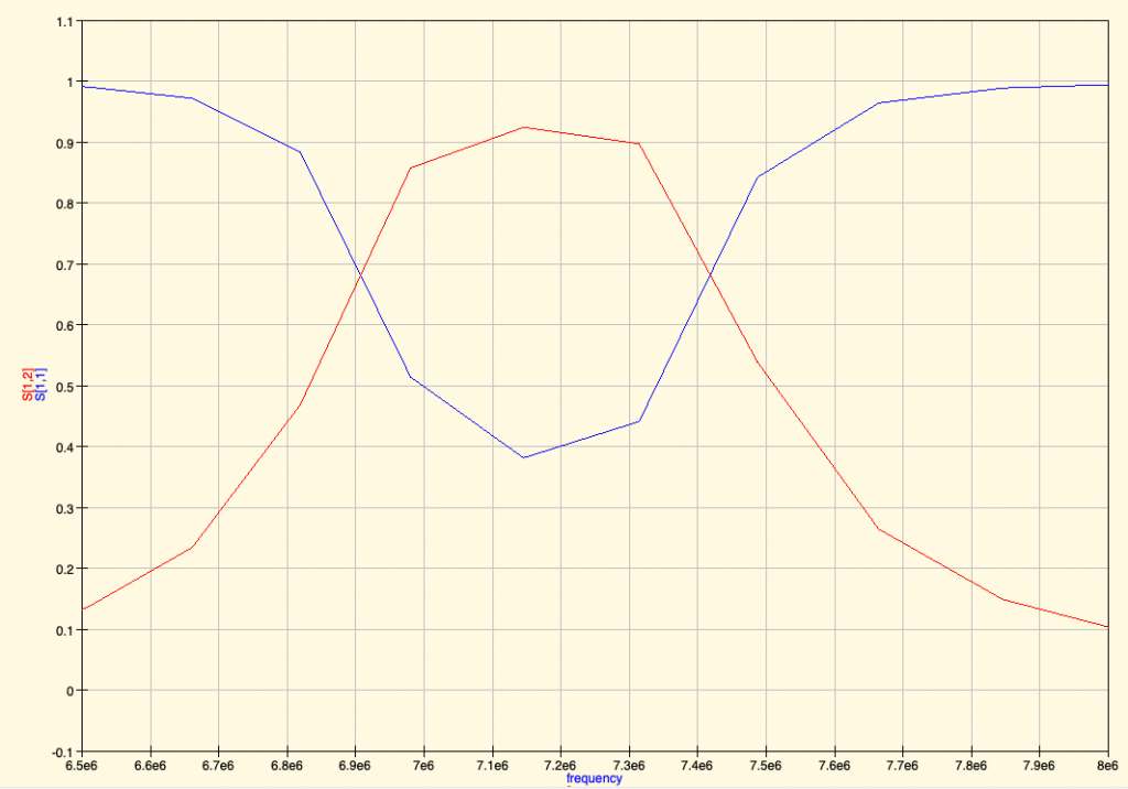
And the corresponding filter simulation output:
This looks acceptable. Or so we think… 😉
Now this is probably not how we should be building filters. And we’re open to suggestions or links to good resource to learn how to do better. It’s for sure not the Electronic Engineer’s way and we’re eager to do better.
Protect the RPi: Schottky Diode
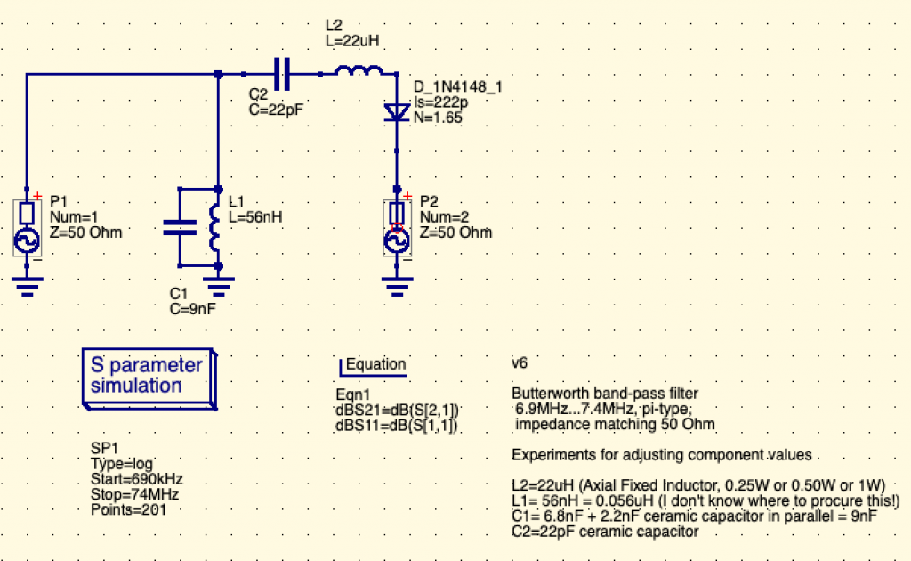
We heard (and felt with our fingers) that antenna can collect some static electricity, and that we may need to protect the RPi against such electricity using a Schottky Diode. Although not classified as Schottky Diode, the 1N4148 signal diode was often quoted as the way to go to protect our RPi. So here we go and added to the schema:
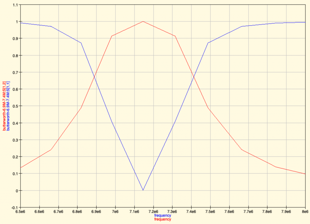
Then we proceed to simulate again to check the resulting graph:
(Even though some error window is displayed before showing Simulation result graph)
We see that the filter’s output seems ok.
Now that’s where we are for now. The schematics are here.
Update for off-the-shelf capacitor values
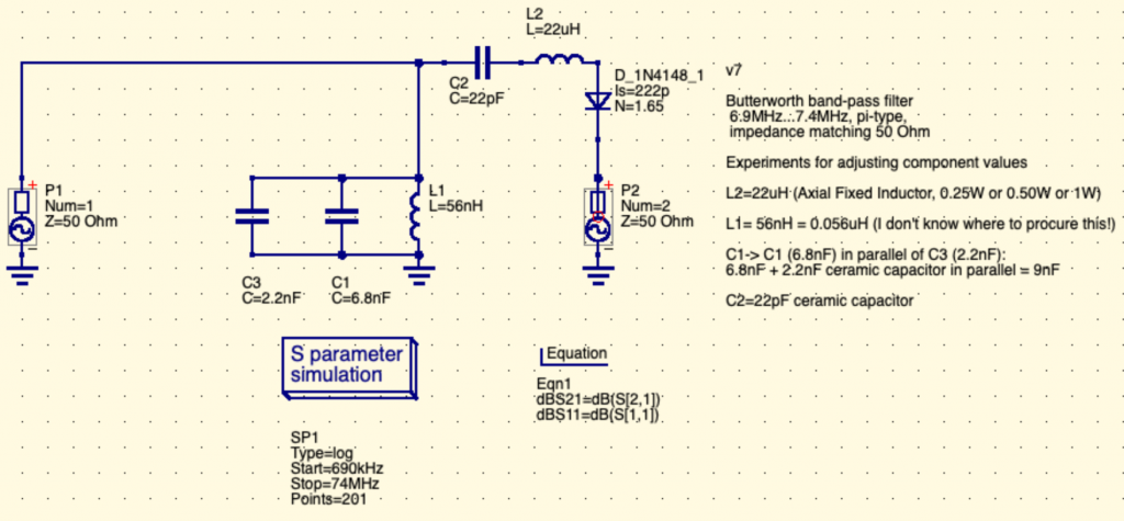
For completeness, here is the v7 with the split C1 capacitor to reflect reality of capacitors values that are easily available in shops:
Here we see that C1 became C1 and C3 (in parallel) to add their values. C1 and C3 (and C2) are standard ceramic capacitors (through hole versions).
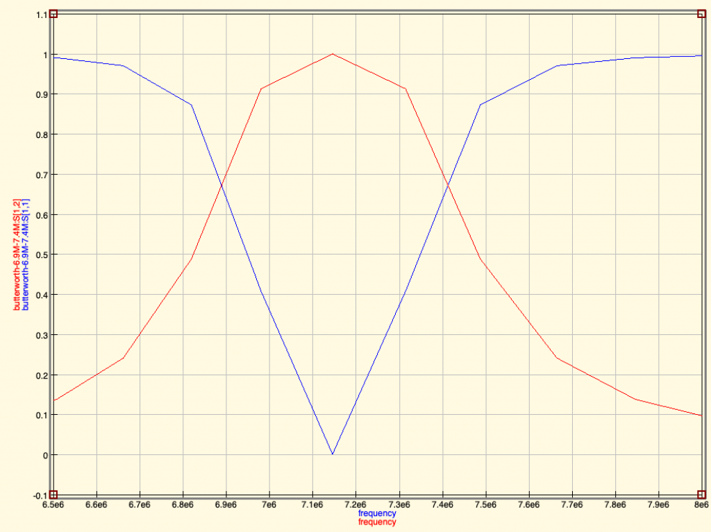
And the resulting simulations gives the same result:
Feedbacks and comments
We’re eager to hear more from you if you have any question or feedback. Please either come to /tmp/lab Matrix chat room: #tmplab:matrix.fuz.re or comment on the reddit link (that will be posted in some time). We also expect to make a short video too to show people how we use QUCS for this.
Next episodes:
Building the filter: soldering, components, testing
Antenna connections and measurements with NanoVNA
Setting up antennas, safety considerations, emitted power
Building our next antenna(s)
Testing the reach of WSPR weak signals
In the meantime, kind regards and please, come and participate. There are no stupid questions. There are no bad feedbacks (but please be kind 😉 ).
Feedbacks and discussion
Ah… that’s awesome, the power of internet community, already just a few minutes after publishing some kind souls gave comments about the design and very informative resources, so I’ll take them point by point here.
Feedback #1: LPF
I would have used a low pass filter, not bandpass.
Yes, we tried some LPF (Low Pass Filter) designs and failed at getting a nice output (the cut-off was very slow and the levels not great). What kind of LPF would be best for this application? (as indeed it sounds like a good candidate)
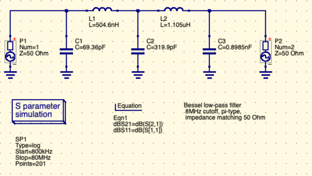
Here is a LPF design (along the lines of what the links below advised):
Two inductors, 3 capacitors. Here without optimized values for easy procurement.
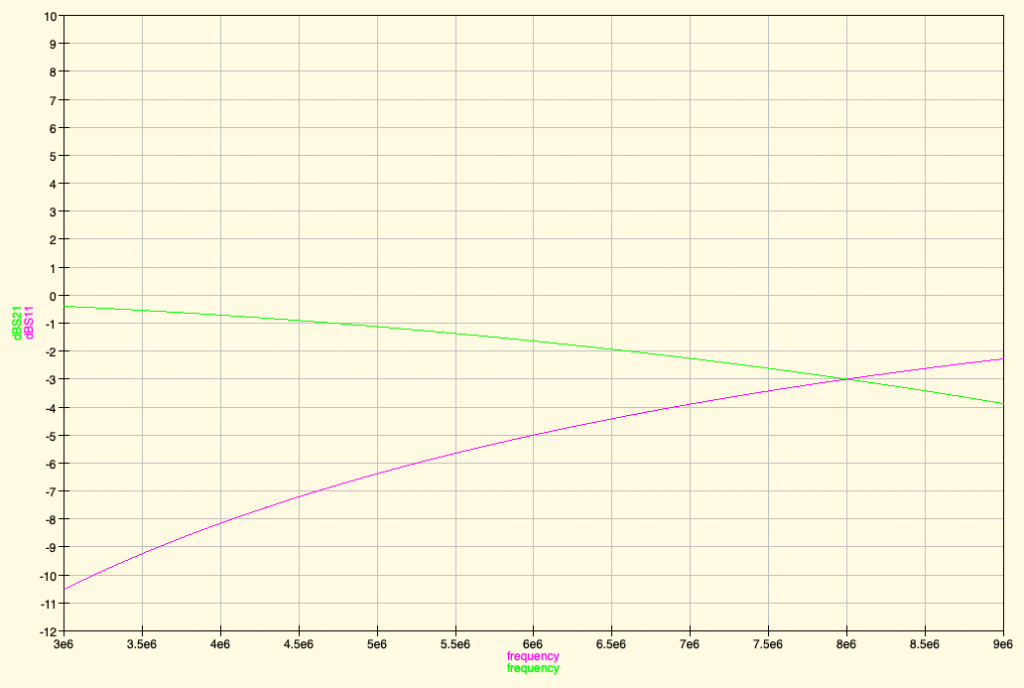
And then the simulation results (here we use dBS11 and dBS21 data lines to plot relative power drop in dB. Have a look at this table to understand the relationship between dB and power multiplier. To remember easily, +3dB is double the power, -3 dB is half the power. +6dB is 4 times the power, etc..):
What I subjectively find is that the cutoff frequency isn’t very “sharp” in simulation (supposedly it’s sharper in reality), and with the same amount of electronic components as a Band Pass Filter (BPF). Not sure what the benefit of the LPF would be.
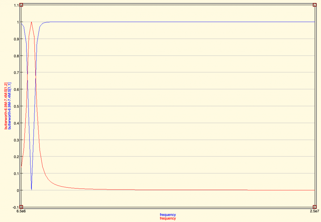
What do you see if you model your filter at 2x and 3x the working frequency?
Here is the simulation result of our BPF (Butterworth Band Pass Filter) with very wide band, not sure that’s what was asked:
No bad effect in simulation… but that’s only a sim of course. Reality sometime differs wildly!
Feedback #2: Diode as harmonics source 🙁
Also not sure you should have the diode protection. Diodes cause harmonics so as quickly as you try to filter them you have placed a device to create more 🙁
Hmm…. how to test for this? Would the simulation show such harmonics Indeed it will be easy to test in reality.
It’s easy to add or take off anyway in the resulting circuit.
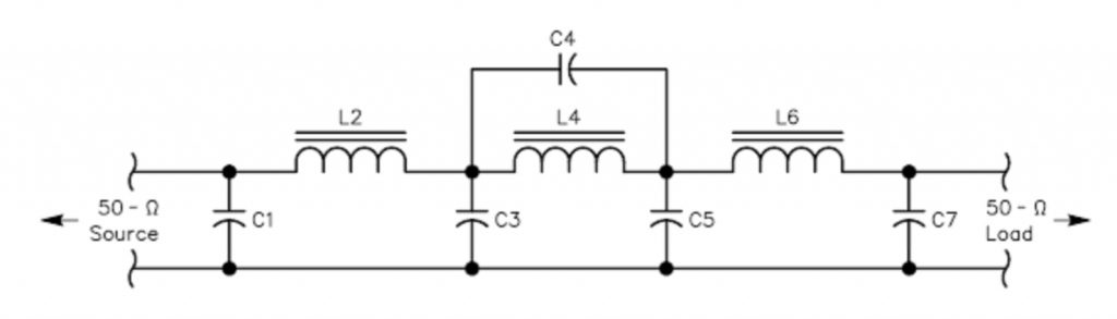
Maybe take standard values for low pass filters from webpages like http://www.gqrp.com/technical2.htm then change the inductance values to the nearest standard value fixed components?
3 inductors and 5 capacitors is definitely a doable and simple enough filter circuit, even if a little bit more complex than our DIY design, but in all probability more reliable and clean. The Capacitor symbol seems to indicate that it’s polarized capacitors that are used. Any feedback how important it is to use polarized capacitors here?
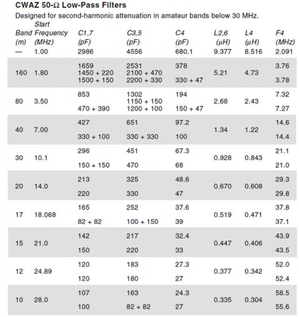
The band table values for components gives also the commercially available component values:
Also some nice ARRL article about the CWAZ filters mentioned in the above resources.
Reading about these filters the CWAZ filters advised by GQRP seems to be advised because of the inadequate filtering of Chebyshev LPF when power levels greater than 5W (FCC requires transmitter spurious outputs below 30 MHz to be attenuated by 40 dB or more for power levels above 5W)
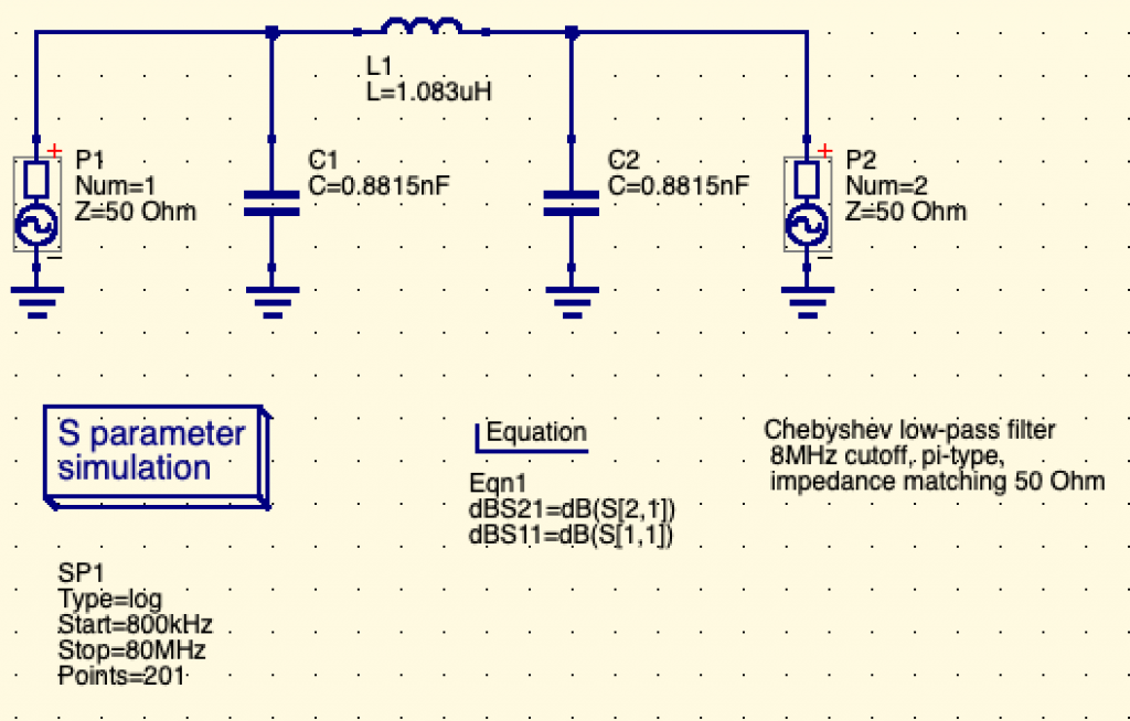
In our case, the power levels are far less than 5W, so actually we could maybe use a simple Chebyshev 3rd order Low Pass Filter and that could be good enough. The filter synthesis result of such LPF could be as simple as:
With resulting filter simulation:
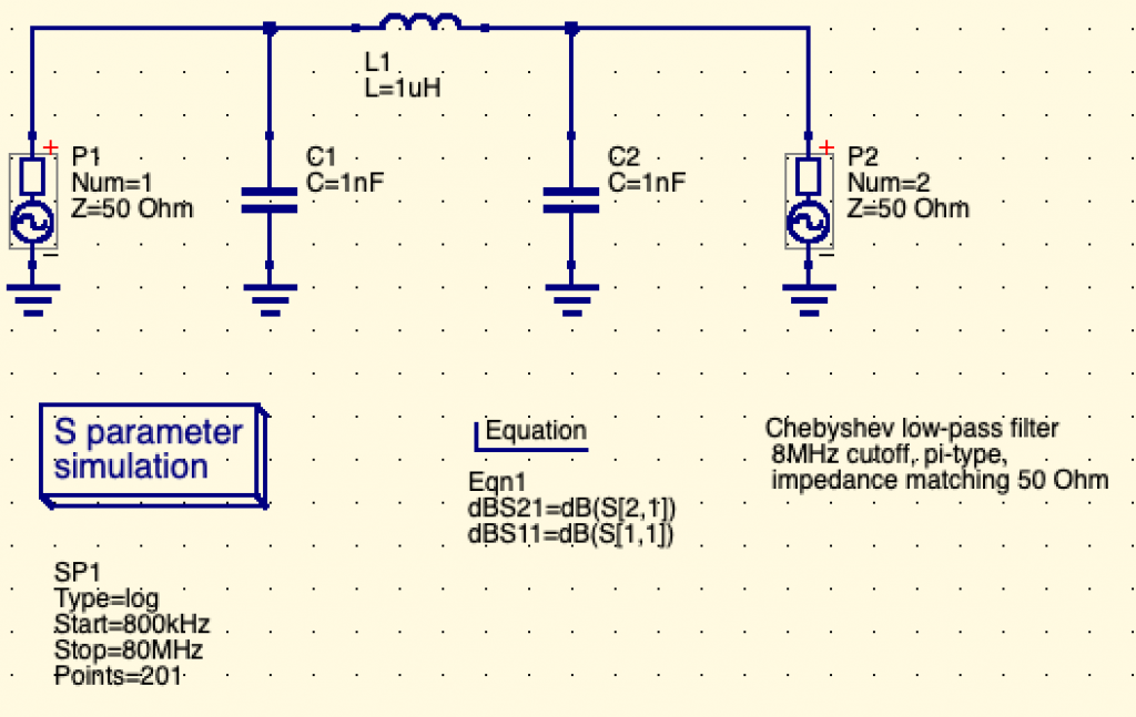
Now when we adjust to available component values, this gives:
lc-ladder-pi-chebyshev-lpf-3rd-order-8MHz-v3.sch
How simple, 2x capacitor of 1nF, 1 inductor of 1uH. Now we’ll see if this fairy tale matches the reality of what we need once implemented 😉
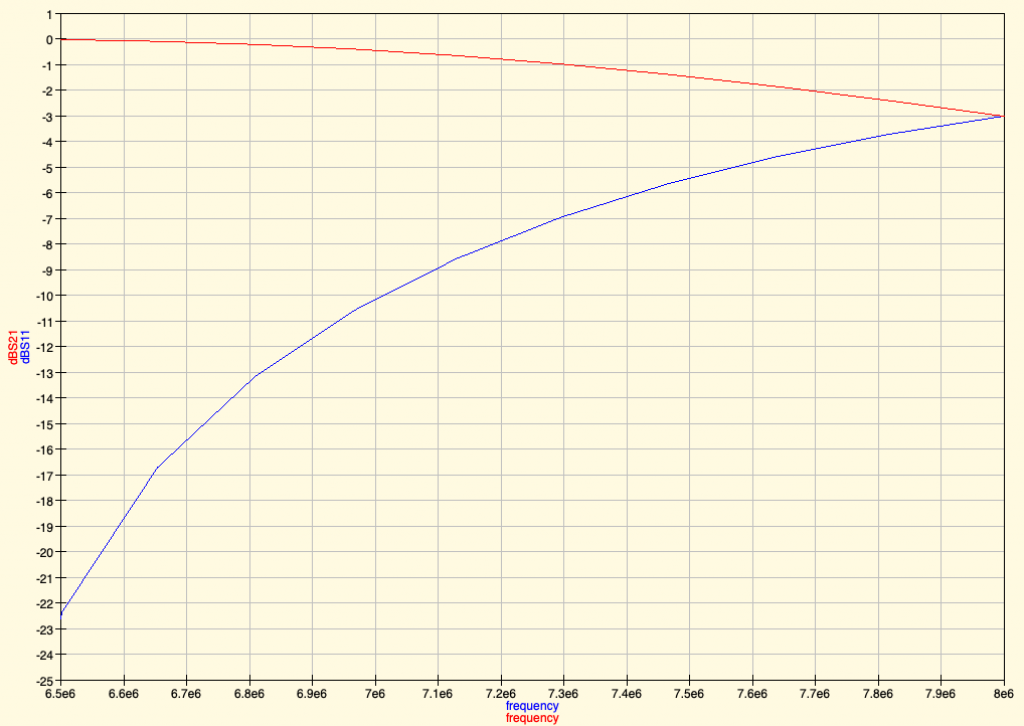
It simulates to:
Which seems pretty much acceptable. Do you think the same? Tell us.
Feedback #4: Filter may not filter enough at higher frequencies
The filtering of our simple filters may not be enough: the roll-off, that is the drop after the cutoff frequency, may not be steep enough.
Filters use often multiple “poles”, that is multiple Inductor+capacitor “legs” to the ground, in order to filter more (e.g. to -60dB or more) at higher frequencies. The more poles (the “higher order” filter), the steeper roll-off, the more attenuation of signal at higher frequencies.
More filtering means less spurious frequencies. And that is the goal of a better filter. Indeed, that’s the role of the CWAZ filter.
Note that Chebyshev filters use order 3, 5, 7 (odd numbers) only when doing filtering synthesis of a passive filter (i.e. one that you don’t need to supply external electricity power supply to work).
So that means that we may either try such filter synthesis…. or use the CWAZ filter that is quite simple still.
Now the problem is to try to use very standard values for electronic components.
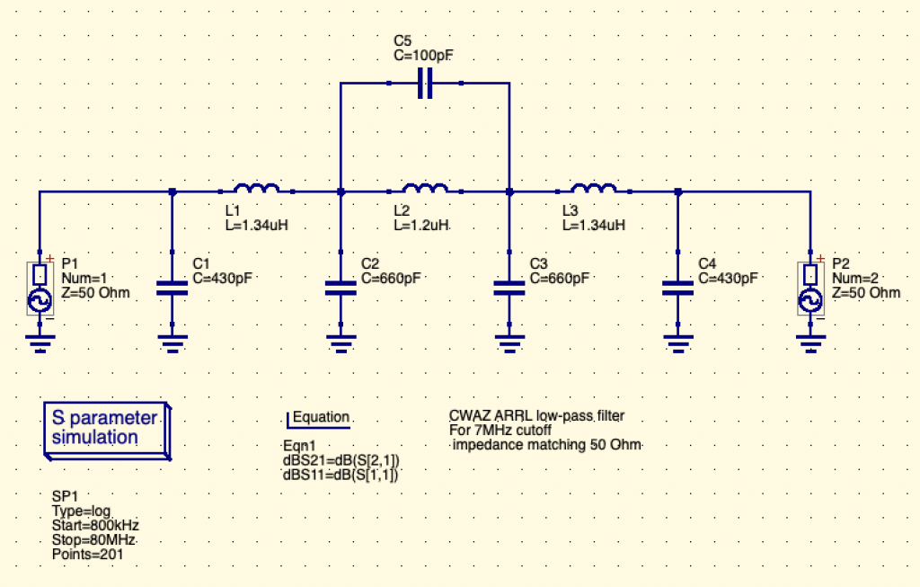
Here for 7MHz, it’s a bit easier as 430pF is 330pF (standard) + 100pF (standard) in parallel. And 660pF is two 330pF capacitor (standard) in parallel.
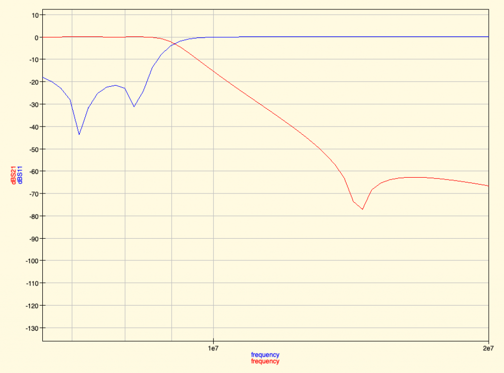
The resulting filter graph is actually very good:
Red line is the output of the filter. 1e7 = 10 MHz. 2e7 = 20MHz, so we see that around 9 MHz the signal starts to be filtered. And that a -70dB filtering means the power level was divided by 10 million 🙂
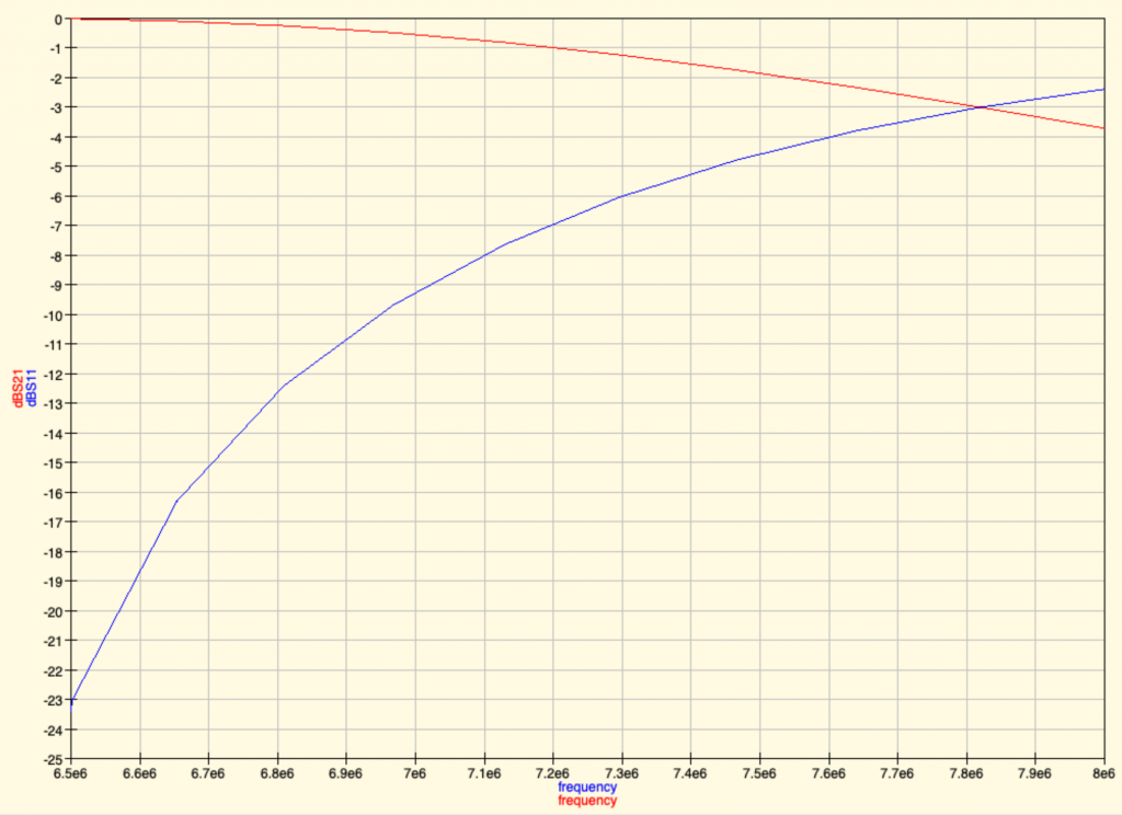
The inductor value of 1.34 uH is not at all easy to find in already prepared packages. If we replace this 1.34uH inductor by a 1.2uH inductor, there’s a risk for a mismatch impedance (meaning your antenna may reflect back some part of the signal to the raspberry pi and damage its circuit components). Ahh… so either we don’t filter enough or we risk having reflected signal from the antenna to the transmitter. What a wonderful world 😉
Future
The new plan is to try to build both our first DIY designed Butterworth BPF filter, the CWAZ and the LPF Chebyshev filter and evaluate these.
We’ll improve this article when finished studying these ressources! Thanks to everyone who is providing feedbacks and ressources!
Thank you
Thanks to the following awesome people who helped either with Radio or with the resources to post and document this exploration:
Covid19 won’t block us! So let’s go virtual. We’re going to organize a virtual Kubernetes Security tech session soon so that interested people can join and share experiences about this. Goal is to look into:
Seccomp
AppArmor
Capabilities
Nodes isolation and security
Admission controllers
K8S Scheduler and controller
APIs Security
Misc CNCF projects such as:
Vitess
Jaeger
Lyft’s Clutch
Spotify’s Backstage
KOPS
For now, best way to show your interest is to join a newly created RIOT Element chat room #tmplab-public and say you’d like to participate.
Depending on interest, we’ll chose a date for start. We’ll then update this page (or post a new one) to announce dates and start.
It’s all about CI these days: Jenkins, Buildbot, numerous SaaS service embedding these fine FLOSS and hoping for a recurring credit card based subscription,… and for a reason. Continuous Integration allow for quicker feedback, shorter dev iterations, better communication.
The principle is simple: as soon as their is a change in code, configuration, datasets, automatically retest the whole application and send automated output (and diffs from previous runs, dashboard, etc..)
Yet, Jenkins or else CI solution, everything takes time to setup. Here with this same principle of CI but with simple bash-one liner, here on Mac:
brew install fswatch
fswatch my_dev_script.py | while read a; do echo “========= Executing $a at `date +%Y%m%d-%H%M`”; $a; echo “========= Done $a”; done
Simple and Stupid right? As soon as the file is changed, fswatch (or inotifywait on Linux) will let the loop run and a new run of your code will happen. Soon enough, you’ll see that every development, no matter how small should always gets its CI.
Then you can go a bit further as when you code, you don’t necessarily always look at your terminal where CI is running. So actually you can track the runs with various metrics into a text/CSV file generated through your one-liner:
Date of run
PID (as it is often sequential)
Number of lines in your source code
Latest GIT commit hash
Number of lines in output
Number of lines matching (case insensitive) “error|warning|traceback|exception”
Input file name for your program
The sky is the limit (please pronounce with a thick Texan accent).
TL;DR if you’re lucky and everything is installed right and you don’t want to understand deeper, try:
vagrant init ubuntu/trusty64
vagrant up
First, let’s install Vagrant on the host computer (a MacOS X Mavericks here, using Homebrew Cask that can install binary install packages):
brew cask install vagrant
Then let’s create a directory where we’ll store the Vagrant related file for this host:
mkdir -p ~/dev/vagrant_trusty
cd ~/dev/vagrant_trusty
Create the shared folder
mkdir vagrant-docker
And let’s create this “Vagrantfile” file to describe our new VM in the Vagrant language:
Vagrant.configure(“2”) do |config|
config.vm.box = “trusty”
config.vm.box_url = “https://cloud-images.ubuntu.com/vagrant/trusty/trusty-server-cloudimg-amd64-juju-vagrant-disk1.box”
# we’ll forward the port 8000 from the VM to the port 8000 on the host (OS X)
config.vm.network :forwarded_port, host: 8000, guest: 8000
config.vm.synced_folder(“vagrant-docker”, “/vagrant”)
# add a bit more memory, it never hurts. It’s VM specific and we’re using Virtualbox here.
config.vm.provider :virtualbox do |vb|
vb.customize [“modifyvm”, :id, “–memory”, 2048]
end
end
Now it’s done, we can create the VM:
$ vagrant up
Bringing machine ‘default’ up with ‘virtualbox’ provider…
==> default: Box ‘trusty’ could not be found. Attempting to find and install…
default: Box Provider: virtualbox
default: Box Version: >= 0
==> default: Adding box ‘trusty’ (v0) for provider: virtualbox
default: Downloading: https://cloud-images.ubuntu.com/vagrant/trusty/trusty-server-cloudimg-amd64-juju-vagrant-disk1.box
default: Progress: 0% (Rate: 1271k/s, Estimated time remaining: 0:08:32)
default: Progress: 1% (Rate: 1532k/s, Estimated time remaining: 0:07:15)
default: Progress: 41% (Rate: 1520k/s, Estimated time remaining: 0:04:10)
default: Progress: 81% (Rate: 1532k/s, Estimated time remaining: 0:01:18)
default: Progress: 84% (Rate: 1545k/s, Estimated time remaining: 0:01:06)
==> default: Successfully added box ‘trusty’ (v0) for ‘virtualbox’!
==> default: Importing base box ‘trusty’…
==> default: Matching MAC address for NAT networking…
==> default: Setting the name of the VM: vagrant_default_1407250776484_38665
==> default: Clearing any previously set forwarded ports…
==> default: Clearing any previously set network interfaces…
==> default: Preparing network interfaces based on configuration…
default: Adapter 1: nat
default: Adapter 2: hostonly
==> default: Forwarding ports…
default: 22 => 2122 (adapter 1)
default: 80 => 6080 (adapter 1)
default: 8001 => 18123 (adapter 1)
default: 22 => 2222 (adapter 1)
==> default: Running ‘pre-boot’ VM customizations…
==> default: Booting VM…
==> default: Waiting for machine to boot. This may take a few minutes…
default: SSH address: 127.0.0.1:2222
default: SSH username: vagrant
default: SSH auth method: private key
default: Warning: Connection timeout. Retrying…
==> default: Machine booted and ready!
==> default: Checking for guest additions in VM…
==> default: Configuring and enabling network interfaces…
==> default: Mounting shared folders…
default: /vagrant => /Users/user/dev/vagrant/vagrant-docker
==> default: Running provisioner: shell…
default: Running: inline script
==> default: You have not informed bzr of your Launchpad ID, and you must do this to
==> default: write to Launchpad or access private data. See “bzr help launchpad-login”.
==> default: Branched 13 revisions.
==> default: Bootstrapping Juju…
==> default: uploading tools for series [precise trusty]
==> default: Logging to /home/vagrant/.juju/local/cloud-init-output.log on remote host
==> default: Bootstrapping Juju machine agent
==> default: Starting Juju machine agent (juju-agent-vagrant-local)
==> default: Taking a nap to let state server come up…
==> default: Added charm “cs:trusty/juju-gui-3” to the environment.
==> default: Setting up Juju GUI dependencies…this may take a minute.
==> default: You can find the log in /var/log/juju-setup.log
==> default: You have not informed bzr of your Launchpad ID, and you must do this to
==> default: write to Launchpad or access private data. See “bzr help launchpad-login”.
==> default: Branched 25 revisions.
==> default: Taking a nap to let Juju Gui get setup
==> default:
==> default: Setting up transparent redirect for Juju-Gui
==> default: Redirecting localhost:80 to 10.0.3.77:80
==> default:
==> default: Executing: sudo iptables -t nat -A PREROUTING -p tcp –dport 8001 -j DNAT –to 10.0.3.77:80
==> default: Executing: sudo iptables -t nat -A POSTROUTING -j MASQUERADE
==> default:
==> default: From your browser on your hosts, you should be able to
==> default: access the GUI by going to: http://127.0.0.1:6080
==> default:
==> default: Your password is: XXXXXXXX
==> default: juju-gui start/running, process 13405
==> default: juju-gui start/running, process 13405
Watch out, your Vagrantfile is **not the only one** being used when bringing up a Vagrant box/instance.
When you get this:
~/dev/vagrant user$ vagrant reload
Vagrant cannot forward the specified ports on this VM, since they
would collide with some other application that is already listening
on these ports. The forwarded port to 8001 is already in use
on the host machine.
To fix this, modify your current projects Vagrantfile to use another
port. Example, where ‘1234’ would be replaced by a unique host port:
Sometimes, Vagrant will attempt to auto-correct this for you. In this
case, Vagrant was unable to. This is usually because the guest machine
is in a state which doesn’t allow modifying port forwarding.
~/dev/vagrant user$
You are actually not only using the Vagrantfile from ~/dev/vagrant but also the one from your “box” distribution .box file which is typically located here:
Vagrant.configure(“2”) do |config|
# This Vagrantfile is auto-generated by ‘vagrant package’ to contain
# the MAC address of the box. Custom configuration should be placed in
# the actual ‘Vagrantfile’ in this box.
# Load include vagrant file if it exists after the auto-generated
# so it can override any of the settings
include_vagrantfile = File.expand_path(“../include/_Vagrantfile”, __FILE__)
load include_vagrantfile if File.exist?(include_vagrantfile)
So, go ahead and edit this file to remove the offending colliding forwarding port(s):
$ vagrant up
Bringing machine ‘default’ up with ‘virtualbox’ provider…
==> default: Importing base box ‘trusty’…
==> default: Matching MAC address for NAT networking…
==> default: Setting the name of the VM: vagrant_default_1401234565101_12345
==> default: Clearing any previously set forwarded ports…
==> default: Clearing any previously set network interfaces…
==> default: Preparing network interfaces based on configuration…
default: Adapter 1: nat
default: Adapter 2: hostonly
==> default: Forwarding ports…
default: 22 => 2122 (adapter 1)
default: 80 => 6080 (adapter 1)
default: 22 => 2222 (adapter 1)
==> default: Running ‘pre-boot’ VM customizations…
==> default: Booting VM…
==> default: Waiting for machine to boot. This may take a few minutes…
default: SSH address: 127.0.0.1:2222
default: SSH username: vagrant
default: SSH auth method: private key
default: Warning: Connection timeout. Retrying…
==> default: Machine booted and ready!
==> default: Checking for guest additions in VM…
==> default: Configuring and enabling network interfaces…
==> default: Mounting shared folders…
default: /vagrant => /Home/user/dev/vagrant/vagrant-docker
==> default: Running provisioner: shell…
default: Running: inline script
…
Type then:
vagrant ssh
And you will be connected.
Enjoy your Vagrant install of Ubuntu Server 14.04 LTS (Trusty Tahr).
Packaged with this Ubuntu Server 14.04 LTS (Trusty Tahr), you will get Juju and Docker pre-installed. This will enable you to connect to http://127.0.0.1:8001 to access Juju web UI.
So grepping this means you'll get plenty of matches from the data encoding image for the ICON. Chrome, it sucks.
So after exporing bookmark, you need to filter it first through some commands like:
sed 's/ICON=\"[0-9a-zA-Z\:\/\;\,\+\=\"]*//g' < ~/Documents/bookmarks_5_21_14.html > ~/Documents/nbookmarks_5_21_14.html
Oh, but why grepping? well, bookmark search sucks so hard in Chrome (it can’t search on keywords in the URL for example), that you do need to do this to be able to get along.
Why not use XML tools? Well… is it standard? NO. sed and grep are.
Hackito Ergo Sum 2014 is being setup. Created by /tmp/lab and for hacking & security passionate researchers, HES 2014 will be the 5th edition of this conference.
/// Communiqué de presse /// Pour diffusion immédiate ///
Hackito Ergo Sum – Conférence Internationale
2 – 4 Mai 2013
Cité des science de la Villette, Paris, France. http://2013.hackitoergosum.org/
Hackito Ergo Sum ouvre ses porte les 2, 3 et 4 mai prochains pour sa 4eme édition, en un moment historique, celui de la décision entre offenseur ou défenseur dans la sécurité informatique, celui de la mise en œuvre de nos connaissances pour la communication et l’exploration; ou pour celle de la restriction et du traçage.
La conférence présentera entre autres comment les hackers changent le monde par exemple avec le project HackRF “Jawbreaker” [1] qui propose de ne plus seulement écouter et recevoir les ondes radios numériques, mais aussi de les émettre. Qu’est-ce que cela change? Cela veut dire que le matériel radio n’est désormais plus l’apanage de gros fabricants de matériel. N’importe qui peut décider, pourvu qu’il se soit assez penché sur le sujet, de fabriquer le prochain Wifi, la 5G. Qui a dit, “5G, la mobilité sans opérateur?”. Nous parlerons exactement de cela.
Nous montrerons aussi comment des systèmes dit inviolables comme celui de l’iPhone [2] (et de toutes les iChoses) se retrouve aussi cracké que les alarmes et serrures de voitures, parfois grâce à une simple montre [3].
Mais le débat de fond, c’est celui comme nous le disions historique du moment ou beaucoup de hackers sont face à un choix, un dilemme pour certains, de travailler pour la sécurité et la protection de la vie privée de chacun, ou de monétiser leur techniques d’attaques pour fabriquer ces “Exploits militarisés” qui peuvent valoir jusqu’à 500 000 euros l’unité.
Et cela pourquoi? Tout simplement parce que de nouveaux acteurs majeurs de la cyberdéfense sont apparus. Exit les société d’armement des années 90. Les états eux mêmes vont au “pair à pair” en achetant ces codes d’attaques à des individus ou des sociétés. L’objectif final est simple: Amesys a montré ses limites. Les vrais dissidents, les vrais opposants se cachent dans le réseau, protègent leur communication, et la seule manière maintenant efficace pour les espionner est de pénétrer leurs ordinateurs, ou celui de leurs fournisseurs d’accès et opérateurs, afin d’espionner leur communications directement à la source. Qui est visé? L’homme ou la femme politique émergente, qui dérange à gauche comme à droite? Le journaliste qui fait réellement son travail au lieu de reprendre maquillé la dépêche de l’Agence France Pwouesse? L’activiste qui pose les questions qui dérangent?
Face à cela, d’autres hackers continuent la lutte pour une information totale sur les vraies vulnérabilités des systèmes que nous utilisons tous les jours, publiant les vulnérabilités et prouvant les problèmes, forçant les fabricants de matériels et logiciels à corriger les problèmes ainsi mis en exergues, minant et détruisant ainsi les codes d’attaques grâce à la correction des failles, détruisant l’arsenal de codes d’attaques achetés à grand frais par des acteurs gris. Fait intéressant, cette noble quête est partiellement illégale en France et pénalisée par des lois interdisant et sanctionnant la diffusion publique de ces preuves de vulnérabilités, les mêmes utilisés sous forme d’ “exploit” d’attaque par les gouvernements de manière couverte et à leur seule discrétion.
Et bien sur, personne n’est blanc. Les états eux mêmes se font la course à qui accumulera la puissance de frappe en “cyberguerre” la plus imposante, la plus variée, la plus efficace? Les dogmes militaires [4] sur le domaine sont même édités et reconnus. Et les éditeurs de logiciels sont pris entre connivence stratégique avec leur pays père respectifs et la nécessité de répondre et protéger leurs clients en corrigeant les vulnérabilités logicielles précedemment découvertes. Dans ce domaine, nous verrons notamment comment ces mêmes pays font des erreurs monumentales dans la création et le déploiement de leur force de frappe de cyberdéfense grâce à la conférence de Raoul Chiesa [5].
Venez donc voir l’état de l’art, pas seulement de la technologie, mais aussi de la société numérique dans laquelle nous vivons grâce à une quinzaine de conférenciers et d’experts français et internationaux.
Rendez vous le 2, 3, et 4 mai prochain à la Cité des science / UniverScience, Centre de congrès de la Villette, Paris, France.
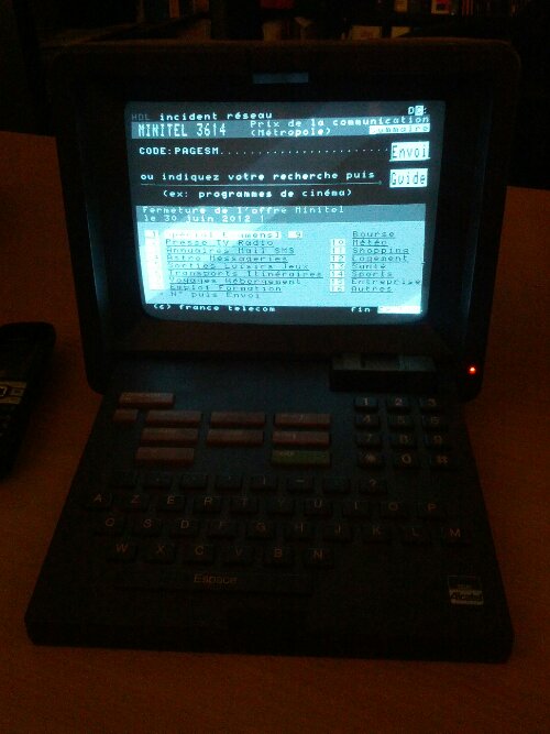
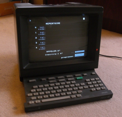
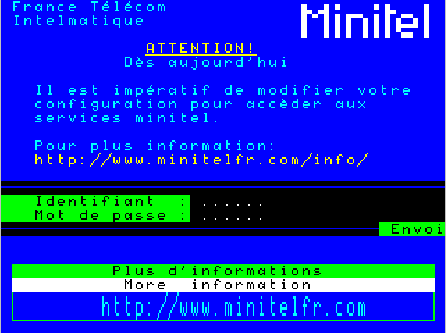
Good bye x25, good bye PAVI, good bye 1200/75, good bye NUI, good bye 3613, 3614 and 3605, good bye V23.
So to celebrate that in due form, based on numerous and precious requests from the best and loved ones, let’s have a paaaarty!
We will investigate the old technology, discuss its fun and its security and insecurity, have some tests and enjoy the whole experience.
Saturday June, 30th 2012 at 21h00 at FUSR-U / AFTER
82 rue du Fbg St Martin
75010 Paris
Metro Chateau d’Eau or Gare de l’Est or Strsbg St Dns or Jcqs Bnsrgnt
*** MINITEL HARDWARE COMPETITION ***
bring your best looking minitel
only working model allowed for competition
*** DEMO TIME ***
bring NUA lists, old and new
bring DECnet hacking manual and PrimeOS primer and Phrack #23 and VM/CMS command lists and CDCnet
bring your Minitel 2 or your latest USB V56 modem, all shiny and V23 compatible.
*** BRAINIAC HACKERS FROM HELL CONTEST QUIZZ ***
There will be a challenge with L33T questions, come and try to see who’s the old school of old school
*** MANUAL VIDEOTEX ARTWORK COMPETITION ***
Come and blow us away with your VIDEOTEX art skills!
This artwork competition will have two categories:
manual and assisted/recorded.
Get this blazing hot!
*** Kink Rose ***
Tell us about your most shameful and heartbreaking stories on Minitel Rose that you had. Public will vote.
Win a “QoTel d’Or”!
*** Bl1tz Talks ***
Come and share your old stories!
there will be some piece about the famous and old
*** APOTHEOSIS ***
yeah, we WILL see the cutoff of this heartwarming Minitel technology at 23:59 give or take a few 100k-philes transfer times.
The Tetalab in Toulouse is a great producer of excellence. Once again they rocked by organizing an amazing event. Fantastic place in Mix’art Myrys, Toulouse. Cool talks and round tables. Plenty of concerts and events. And the workshops from BGP configuration by Tetaneutral, DIY sextoys, Usinette,
Congratulations to the team!
Bitcoin is now breaking records and shows no obvious flaws. We see it combined with silk road and lulzsec accepting donations in bitcoins for their FBI Infraguard and Sony hacks, bringing together FBI, money laudering, new legit alternative currency and a new model for economy without the bankers.
A new hackerspace is born in Buenos Aires, Argentina. Our friends there opened “Fábrica de Inventos” yesterday. They are looking for a more definitive space theree (hint, help them if you’re there) but already they’re up and kicking, organizing a Open Security fair with workshops and activities.
We wish them great success and hope to visit soon, maybe for the next ekoparty conference?.
After a quick browse of packet crafting libraries in Ruby, I got to see the following situation that might interest anyone who would like to craft and send packets in Ruby.
Python pioneered the field mainly with excellent Philippe Biondi’s scapy that got so much press and attention. Now, with Metasploit and various other tools being developped in Ruby, we have more and more reasons to focus on Ruby for this kind of activity, so what do we have at our disposal for such tasks, here is a little recap of the main projects:
Racket : the one being currently used by Metasploit and modeled after libdnet. Still being actively developped.
PacketFu : PacketFu is trying to make a come back into Metasploit by providing the same protocol support at Racket does. Still being actively developped.


![Kubernetes Security tech session [Upcoming]](https://www.tmplab.org/wp-content/uploads/2020/07/k8s-matrix.png)